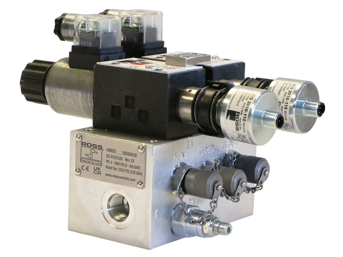
HBB HBB Series
- Each main valve in the HBB Series system is equipped with an inductive position switch.
- Monitoring of these switches is to be done by an electrical safety control system.
- Redundant spool type valve system
- Tamper-evident relief valve available on inlet
- Special tamper resistant tool required for disassembly
- Inline mounting with SAE threaded ports on D03 & D05 sizes. Flange ports on D07 size.
loading...
loading...
Product Overview
The ROSS Controls HBB Series is a family of redundant 3/2 hydraulic valve systems engineered to meet the demanding requirements of safe hydraulic block and bleed applications in industrial machinery. The safety function of each HBB valve system is to block hydraulic supply pressure and simultaneously bleed downstream hydraulic energy back to tank, ensuring that actuators and circuits downstream of the valve are fully de-energized before personnel access.
Each HBB valve system contains two independently actuated spool-type valve elements that operate synchronously. Both solenoids must be energized together to allow flow, and the system defaults to the block and bleed state upon loss of electrical power or any single valve fault. Each main valve element is equipped with a PNP inductive position switch, allowing an external electrical safety control system to continuously monitor valve spool position and detect discrepancies between commanded and actual states.
The HBB Series is available in three body sizes (D03, D05, D07) covering flow ranges from 0 to 50 gpm and port sizes from SAE-8 to 1-1/4 Code 61 Flange. Body sizes D03 and D05 use direct solenoid actuation while body size D07 uses solenoid pilot operation for reliable shifting at high flow. An optional tamper-evident relief valve is available on the inlet to protect against downstream pressure buildup. The tamper-resistant design requires a special tool for disassembly, preventing unauthorized modification of the safety system.
Block and Bleed functions are intended to permit flow when switched on and to block supply and bleed off downstream hydraulic energy when switched off or in a faulted state. Engineers must account for the effect of downstream components such as pilot-operated check valves, counterbalance valves, and closed-center directional valves, which may affect the rate and completeness of downstream bleed. The HBB valve is intended for routine, repetitive production tasks. Maintenance tasks require full lockout/tagout procedures per OSHA 1910.147.
Key Engineering Features
- Redundant Dual-Valve Architecture - Two independently actuated 3/2 spool valve elements that operate synchronously. Both solenoids must be energized simultaneously to permit flow; loss of either solenoid or any single fault drives the system to the block and bleed safe state.
- PNP Inductive Position Switches - Two PNP inductive position switches (one per valve element, M12 5-pin A-coded connector) monitor spool position in real time, allowing an external electrical safety control system to detect valve discrepancies and enforce Category 4 / PL e safety architecture when properly integrated.
- Three Body Sizes - D03 (0-10 gpm, SAE-8 ports), D05 (0-20 gpm, SAE-12 ports), and D07 (0-50 gpm, 1-1/4 Code 61 Flange) cover the full range of industrial hydraulic circuit sizes.
- Direct or Pilot Actuation - Body sizes D03 and D05 use direct solenoid operation for fast response at moderate flows. Body size D07 uses solenoid pilot operation to reliably shift high-flow valve elements against the forces generated by 5000 psi hydraulic pressure.
- Tamper-Evident Relief Valve - Optional inlet relief valve preset to approximately 10% above system operating pressure prevents downstream pressure spikes. Tamper-evident design requires a special removal tool, maintaining safety system integrity and preventing unauthorized adjustment.
- Tamper-Resistant Disassembly - Special tamper-resistant tool required for valve disassembly, preventing unauthorized modification of a safety-critical component and maintaining system compliance with applicable machine safety standards.
- Horizontal Base Mount Orientation - Base-mounted design with inline SAE threaded ports on D03 and D05 sizes, and flange ports on D07. Any mounting orientation is acceptable, with horizontal preferred for optimal spool dynamics and drainage.
- Continuous Duty Solenoids - Solenoids are rated for continuous duty per VDE 0580 with EN 175301-803 Form A electrical connections and IP65 enclosure rating, ensuring reliable operation in harsh hydraulic machine environments with exposure to oil mist and coolant.
- Buna-N Seals - Buna-N (nitrile) seals provide compatibility with mineral oil HLP and vegetable oil HETG hydraulic fluids across the recommended operating temperature range of -4 to 140 degrees F for media.
- Ductile Iron Construction - Valve body, manifold, and primary wetted components are constructed from ductile iron with steel spools, providing the structural integrity required for sustained operation at 5000 psi and resistance to the mechanical shock loads present in industrial hydraulic systems.
Technical Specifications
General Specifications
| Parameter | Specification |
| Safety Function | Block & Bleed |
| Valve Type | Directional Control |
| Construction | Redundant Spool Type |
| Valve Function | Dual 3/2 Normally Closed, Spring Return |
| Actuation | Direct Solenoid (D03, D05); Solenoid Pilot Operated (D07) |
| Mounting | Base Mount; any orientation, preferably horizontal |
| Port Configuration | Inline SAE threaded (D03, D05); Code 61 Flange (D07) |
| Monitoring | External (by electrical safety control system) |
| Standard Voltage | 24 VDC |
| Duty Cycle | Continuous Duty |
| Solenoid Connection Type | EN 175301-803 Form A |
| Solenoid Enclosure Rating | IP65 per DIN 40050 |
| Inductive Position Switch Type | PNP, M12 5-pin A-coded (2 per system) |
| Switch Current Consumption (Max) | 400 mA per switch |
| Maximum Operating Pressure | 5000 psi (344 bar) |
| Flow Media | Mineral Oil HLP, HL-DIN 51524; Vegetable Oil HETG - VMDA 24568 |
| Valve Body & Manifold Material | Ductile Iron |
| Spool Material | Steel |
| Seal Material | Buna-N |
Temperature Ratings
Temperature ratings are recommended operating ranges. Operation outside these ranges requires engineering review.
| Configuration | Ambient Temperature | Media Temperature |
| Ambient Temperature | 4 to 160 F (-20 to 71 C) | |
| Media (Hydraulic Fluid) Temperature | 4 to 140 F (-20 to 60 C) |
Important: Hydraulic fluid must be maintained within the recommended temperature range. Fluid viscosity outside the valve design range may affect shifting reliability and spool response time.
Flow Performance Data
Flow rates and weights by body size. All models rated to 5000 psi maximum operating pressure.
| Body Size | Port Size | Flow Rate | Power (each solenoid) | Weight lb (kg) |
| D03 | SAE-8 | 0 to 10 gpm | 30 watts | 22.7 (10.3) |
| D05 | SAE-12 | 0 to 20 gpm | 36 watts | 53.4 (24.2) |
| D07 | 1-1/4 Code 61 Flange | 0 to 50 gpm | 30 watts | 131.9 (59.8) |
Certifications & Compliance
| Certification/Standard | Detail |
| Safety Architecture | Designed for external monitoring. When integrated with a Category 4 / PL e rated external safety control system, enables the highest machine safety performance levels per ISO 13849-1. |
| Functional Safety Design Intent | Redundant dual-valve architecture with independent position monitoring supports SIL 3 / Category 4 / PL e safety architectures when properly integrated per IEC 61508 and ISO 13849-1. |
| Solenoid Standard | Solenoids conform to VDE 0580 for continuous duty rated coils in industrial hydraulic applications. |
| Solenoid Enclosure | IP65 per DIN 40050, providing dust-tight protection and resistance to low-pressure water jets in industrial hydraulic environments. |
| CE Marking | Available on applicable models. Verify with ROSS Controls for specific model CE declaration status. |
| Inductive Switch Standard | Position switches conform to EN 60947-5-2 for inductive proximity switches used in safety-related applications. |
Typical Applications & Industries
Press and Stamping Operations
- Hydraulic press circuits where downstream ram pressure must be fully vented before die change, tooling access, or jam clearance. The HBB valve blocks supply and bleeds the press cylinder circuit, enabling compliant energy isolation.
- Metal stamping lines requiring safe tool access between production cycles. The redundant valve architecture provides the fault-tolerance required for high-consequence press applications.
- Forging press energy isolation between forging cycles when maintenance personnel must access the tooling area or clear material jams.
Injection Molding and Plastics Processing
- Injection molding machines where downstream mold clamp hydraulic pressure must be dumped before mold access for cleaning, part removal jams, or tooling change.
- Extrusion line actuator circuits requiring safe hydraulic isolation before personnel access to die or screen changer areas.
- Hydraulic accumulator circuits where downstream energy must be fully dissipated before safe access, with the HBB valve providing both blocking and bleed functions simultaneously.
Steel and Metal Processing
- Rolling mill hydraulic actuator circuits where downstream pressure must be eliminated before roll change or maintenance access on gap adjustment cylinders.
- Continuous casting machine hydraulic circuits for segment drives and strand guide actuators, where safe energy isolation is required before in-process maintenance tasks.
- Shearing line hydraulic circuits for blade clamping and hold-down cylinders, isolating energy before blade exchange or alignment adjustments.
- Coil handling equipment hydraulic circuits for mandrel, tension reel, and coil car actuators requiring block and bleed isolation during coil transfer operations.
Automotive Manufacturing
- Body shop hydraulic fixture circuits for clamping, locating, and holding actuators where safe access is required between production runs for setup or maintenance.
- Hydraulic assembly press circuits for powertrain component assembly requiring safe energy isolation before part removal or fixture maintenance.
- Hydraulic leak test equipment circuits requiring complete pressure isolation before fixture change or test head access.
General Industrial and Heavy Equipment
- Hydraulic cylinder circuits on special-purpose machines where the block and bleed function ensures downstream actuators cannot move during maintenance access.
- Industrial robot hydraulic brake and counterbalance circuits where residual pressure must be verified as zero before robot arm repositioning during maintenance.
- Hydraulic power unit circuits feeding multiple machine zones, where a single HBB valve provides zone-level energy isolation independent of the main power unit.
Wood Processing and Lumber
- Hydraulic feed rolls and clamping cylinders on saw lines where safe access is required for blade change or board jam clearance.
- Log handling and debarking hydraulic circuits requiring energy isolation before personnel access to infeed and outfeed zones.
- Planer and moulder hydraulic clamping circuits requiring block and bleed isolation before cutterhead access for tooling replacement.
Ordering and Model Number Configuration
The HBB Series uses a structured model number system. Select body size, flow rate, port size, relief valve setting, seal type, and monitoring configuration to build the complete model number.
|
HBB Series Model Number Structure:
HBB D D [Body/Flow/Port] [Relief] B A E X B | | | Series | Body Size / Relief | | Revision Level Flow Rate / Valve Set | | Communication (X = None) Port Code (XX = None)| Monitoring (E = External) Material (D = Ductile Iron) | Seal (A = Buna-N) Voltage (D = 24 VDC) Valve Type (B = Double)
Body/Flow/Port Codes: 108S = D03, 0-10 gpm, SAE-8 212S = D05, 0-20 gpm, SAE-12 371F = D07, 0-50 gpm, 1-1/4 Code 61 Flange
Relief Valve Setting Codes (psi / bar): 11 = 1000/1100 psi | 17 = 1500/1700 psi | 22 = 2000/2200 psi 28 = 2500/2800 psi | 33 = 3000/3300 psi | 39 = 3500/3900 psi 44 = 4000/4400 psi | 50 = 4500/5000 psi | 55 = 5000/5500 psi XX = No Pressure Relief Valve
Example (D03, no relief): HBBDD17108SBAEXB Example (D05, no relief): HBBDD33212SBAEXB |
Relief valve codes represent the maximum system operating pressure at which the relief is preset; factory preset is approximately 10% above the selected system pressure.
Both solenoids must be operated synchronously. The external safety control system must de-energize both solenoids simultaneously on a safety stop command.
Contact ROSS Controls for applications outside the standard operating parameters, including fluids other than mineral oil HLP or vegetable oil HETG.
For system pressure above 5000 psi or flow above 50 gpm, contact ROSS Controls engineering for application review.
Accessories
Electrical Connectors for Solenoids
ROSS Controls offers EN 175301-803 Form A prewired connectors compatible with the HBB Series solenoid connections. Available in cable grip and conduit entry configurations, with and without LED status indication.
| Connection | Cord Length | Cord Diameter | Model (No Light) | Model (24 VDC Lighted) |
| EN 175301-803 Form A Prewired (18 AWG) | 2 m (6.5 ft) | 6 mm | 721K77 | 720K77-W |
| EN 175301-803 Form A Prewired (18 AWG) | 2 m (6.5 ft) | 10 mm | 371K77 | 383K77-W |
| Connector for 1/2" Conduit | 723K77 | 724K77-W | ||
| Connector Only (no cord) | 937K87 | 936K87-W |
Warning: Do not use electrical connectors with surge suppressors. Surge suppressors increase valve response time when de-energizing solenoids, which can delay the transition to the safe (block and bleed) state and compromise safety function response time.
Related Products & Accessories
- HBH Series Hydraulic Block & Stop Valves - Redundant blocking valve systems for safe block and stop of hydraulically controlled cylinders, with poppet-type cartridge valve elements for positive load holding. https://www.rosscontrols.com/en/series/1312-hbh
- HDBH Series Hydraulic Dual Block & Stop Valves - Sandwich-mount redundant dual blocking valve system for D03 manifolds, providing safe stop for hydraulic actuators with flow doubling capability. https://www.rosscontrols.com/en/series/1313-hdbh
- Hydraulic L-O-X Lockout Valve - Manual 4-way hydraulic lockout valve for safe energy isolation per OSHA lockout/tagout requirements, with bypass of pump flow and bleed of downstream pressure. https://www.rosscontrols.com/en/series/3133-hydraulic-lockout-valve
- ElectroGuard Energy Isolation System - Integrated electrical, pneumatic, and hydraulic energy isolation system with remote lockout stations, certified to Category 4 / PL e. https://www.rosscontrols.com/en/series/1314-electroguard
- DM2 Series Pneumatic Double Valves - Control-reliable pneumatic double valves for Category 4 / PL e safe exhaust applications in machine guarding. https://www.rosscontrols.com/en/categories/529-hydraulic
Frequently Asked Questions (FAQ)
Q: What is the safety function of the HBB Series valve?
A: The safety function is Block and Bleed. When the valve is de-energized (or in a faulted state), it simultaneously blocks hydraulic supply pressure from reaching the downstream circuit and bleeds any residual downstream hydraulic pressure back to tank, ensuring the downstream actuators are fully de-energized.
Q: How does the HBB valve differ from a simple shutoff valve?
A: A single shutoff valve provides only blocking without bleed and offers no redundancy. The HBB Series provides redundant dual-valve architecture, active downstream bleed, and inductive position switch monitoring for each valve element, enabling integration into external safety control systems that can verify the valve is in the correct state before permitting safe access.
Q: What does external monitoring mean?
A: External monitoring means the valve system itself does not contain the safety logic. Instead, the two PNP inductive position switches send spool position signals to an external electrical safety control system (such as a safety PLC or safety relay), which monitors for discrepancies and initiates a machine stop if both spools are not in the expected position within a defined time window.
Q: Can downstream PO check valves or counterbalance valves affect the bleed function?
A: Yes. Pilot-operated check valves, counterbalance valves, and closed-center directional valves are designed to block flow under certain conditions. If such components are present downstream of the HBB valve, they may slow or prevent complete bleeding of downstream pressure. The system designer must evaluate whether additional bleed paths or different downstream component configurations are required to achieve the required safe state.
Q: What safety category and performance level can be achieved with the HBB Series?
A: When properly integrated with a Category 4 / PL e rated external safety control system that monitors the position switches and controls the solenoids, the combined system can achieve Category 4 / PL e performance per ISO 13849-1. ROSS Controls provides functional safety data to support system-level calculations.
Q: What hydraulic fluids are compatible with the HBB Series?
A: The HBB Series is compatible with mineral oil hydraulic fluid per HLP, HL-DIN 51524 and vegetable oil HETG per VMDA 24568. For other fluid types, contact ROSS Controls engineering to confirm seal compatibility and applicability.
Q: What is the maximum operating pressure for the HBB Series?
A: The maximum operating pressure is 5000 psi (344 bar) across all body sizes. The inlet relief valve option can be set from 1100 psi up to 5500 psi factory preset, depending on the system operating pressure selected.
Q: Why must both solenoids be operated synchronously?
A: Synchronous operation ensures both valve elements shift together. If one solenoid is energized while the other remains de-energized, the position switch monitoring system will detect the discrepancy and signal a fault condition to the external safety control system, preventing inadvertent partial actuation that could compromise the safety function.
Q: What is the purpose of the tamper-resistant design?
A: The tamper-resistant design prevents unauthorized personnel from disassembling or modifying the valve system. A special tool is required for disassembly. This maintains the integrity of the safety function and prevents bypassing of the redundant architecture, which is critical for sustained compliance with machine safety standards.
Q: Can the HBB valve be used for long-term load holding?
A: No. The HBB valve is a spool-type valve and, like all spool valves, has inherent internal leakage. It is designed to bleed downstream pressure, not to hold a load in position for extended periods. For long-term load holding, additional components such as counterbalance valves or pilot-operated check valves must be incorporated downstream of the HBB valve.
Q: Is the HBB valve suitable for maintenance tasks?
A: The HBB valve is designed for routine, repetitive production tasks such as enabling safe access between production cycles. For maintenance tasks that require sustained energy isolation (such as replacing hydraulic components), full lockout/tagout procedures per OSHA 1910.147 must be followed, including isolation at the main hydraulic power unit and installation of lockout devices on all energy sources.
Q: What is the difference between D03, D05, and D07 body sizes?
A: Body sizes refer to the ISO valve envelope size and determine the flow capacity. D03 handles 0-10 gpm with SAE-8 ports, D05 handles 0-20 gpm with SAE-12 ports, and D07 handles 0-50 gpm with 1-1/4 Code 61 Flange ports. D07 uses solenoid pilot actuation rather than direct solenoid actuation due to the higher shifting forces required at large flow capacity.
Q: What position switch signal interface is required from the external safety controller?
A: Each position switch is a PNP type with an M12 5-pin A-coded connector. The switch outputs are normally open (NO) and normally closed (NC). The external safety control system must monitor both switch states and detect cross-faults or discrepancies within the required safety-function response time.
Installation & Maintenance Guidelines
- Mount in any orientation; horizontal mounting is preferred for optimal spool dynamics and contamination drainage from the manifold.
- Ensure hydraulic fluid cleanliness meets ISO 4406 Class 16/14/11 or better. Contaminated fluid can cause spool sticking and switching delays that compromise safety function response time.
- Both solenoids must be wired to operate synchronously. Never energize one solenoid independently during normal operation. Use a safety-rated output module to control both solenoids simultaneously.
- Wire both inductive position switches to the external safety control system. The safety controller must monitor for discrepancies between the two switch signals and respond within the required stopping time of the machine.
- Do not use electrical connectors equipped with surge suppressors. Surge suppressors slow solenoid de-energization, which increases response time to the safe state.
- Verify the inlet relief valve setting matches the maximum system operating pressure before commissioning. The relief valve is factory preset at approximately 10% above the ordered system pressure.
- Torque all port fittings to the SAE or Code 61 flange specification. Under-torqued fittings can result in external leakage at full system pressure.
- After installation, cycle the valve several times under full system pressure and verify position switch outputs are transitioning correctly before integrating with the safety control system.
- For system maintenance requiring valve removal, follow full lockout/tagout procedures including hydraulic power unit isolation and accumulator discharge before breaking any hydraulic connections.
- Periodically inspect the tamper-evident relief valve seal and position switch connections for signs of tampering, loosening, or damage. Document inspection results as part of the machinery safety maintenance program.
Warranty & Global Support
ROSS Controls provides a one-year warranty on all products, covering defects in material and workmanship from the date of purchase.
Global technical support is available through ROSS Controls offices in the USA (headquarters in Ferndale, Michigan), Canada, Brazil, Germany, France, United Kingdom, India, China, and Japan.
Contact ROSS Controls USA at +1-248-764-1800 or (800) 438-7677, or visit rosscontrols.com for product configuration, application engineering support, and distributor locator services.
For complete technical data, dimensional drawings, functional safety data, and valve selector access, visit the ROSS Controls HBB Series product page at rosscontrols.com.
Download Catalog: https://www.rosscontrols.com/en/series/1311-hbb
Download Documents
HBB
